
GD&T Position Tolerance Calculator
Stated tolerance, MMC bonus and measured true position in one sheet.

About this resource
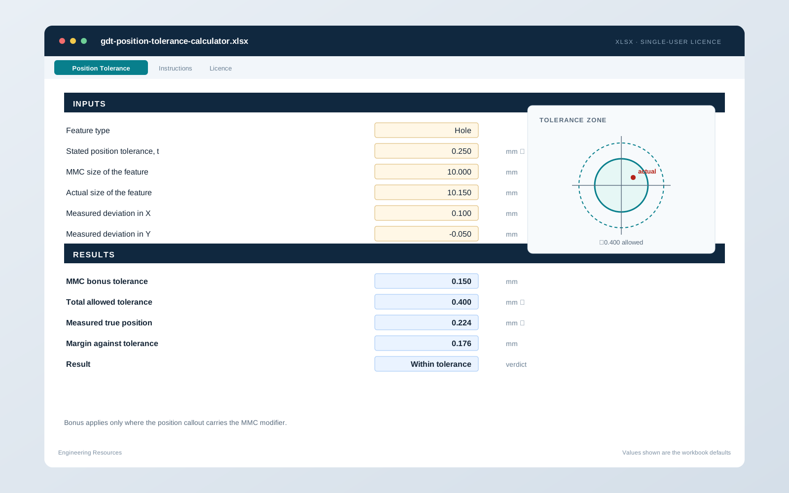
This workbook handles the position tolerance calculation that appears on a large share of mechanical drawings: a diametrical position zone applied to a hole or a shaft, with the maximum material condition modifier.
Enter the stated tolerance, the MMC size, the actual produced size and the measured deviation from true position in X and Y. The sheet returns the MMC bonus, the total allowed tolerance, the measured true position, the remaining margin and a clear within or out of tolerance verdict. It also gives the equivalent ± coordinate tolerance for drawings or reports that use square zones.
The bonus explanation states when the MMC modifier applies and when it does not. Datum shift, projected tolerance zones and orientation refinements are outside the scope and are listed as limitations.
Use the workbook for inspection review, drawing interpretation and training. Confirm the drawing's datum scheme and the applicable standard before accepting or rejecting a part.
What is included
- GD&T Position Tolerance Calculator — XLSX · Position tolerance calculator for holes and shafts, with MMC bonus, true position, margin, verdict, assumptions and licence sheets. · Editable
- Hole and shaft feature selector
- MMC bonus and total allowed tolerance
- Measured true position from X and Y deviations
- Margin and within or out of tolerance verdict
- Equivalent ± coordinate tolerance
- Bonus explanation, assumptions, instructions and licence sheets
Software compatibility
- Microsoft Excel: Excel 2016 or later, desktop or Microsoft 365 · required · edit · tested by author — Uses standard square-root and conditional functions.
- LibreOffice Calc: 7.6 or later · optional · edit · format based expectation — Opens normally; check the printed layout before using it as an inspection record.
Prerequisites and technical context
Intended audience
working-engineer, engineering-team, early-career-engineer, student
Prerequisites
- The feature control frame and datum scheme from the drawing
- Measured feature size at MMC
- Measured X and Y deviation from true position
Unit systems
- Metric: mm
Assumptions
- A single feature measured at one axial plane
- Axis-parallel X and Y deviations from the true position
- Position callout carries the MMC modifier where bonus is used
- No datum shift, projected tolerance zone or orientation refinement
- Actual size is measured within the drawing limits
Technical notes
- MMC bonus for a hole = actual size − MMC size, never below zero.
- MMC bonus for a shaft = MMC size − actual size, never below zero.
- Measured true position = 2 × √(X² + Y²) for a diametrical zone.
- Equivalent ± coordinate tolerance = total tolerance / (2 × √2) for a square zone that fits inside the diametrical zone.
References
- No external standards or references listed.
Scope and limitations
Included
- Hole and shaft feature selector
- MMC bonus and total allowed tolerance
- Measured true position from X and Y deviations
- Margin and within or out of tolerance verdict
- Equivalent ± coordinate tolerance
- Bonus explanation, assumptions, instructions and licence sheets
Not included
- Datum shift and datum reference frame analysis
- Projected tolerance zones and orientation refinements
- Virtual condition and functional gauge design
- Full GD&T tolerance stack-up analysis
- Certification of an inspection result
Limitations
- The result depends on correct measurement of feature size and axis deviation.
- The workbook does not interpret the drawing for you; confirm the datum scheme and modifiers.
- Use the applicable drawing standard and a qualified inspection process before accepting or rejecting production parts.
Author and review information
Author / publisher: Engineering Resources
Review status: Author checked
The calculation follows the standard diametrical position tolerance relationship and the maximum material condition bonus rule. The worked default is a hole at MMC plus 0.150 mm with a small X/Y deviation.
Review scope: Formulas, worked defaults and stated assumptions were checked against the classical equations named on each sheet. No independent third-party review was commissioned.
Licence and permitted use
Single-user commercial licence
One named user may use this resource on any number of their own devices for commercial and educational engineering work. Resale, redistribution, publication, sublicensing and inclusion in a paid course or product are not permitted. Adapted copies remain subject to the same terms.
- Use on your own projects, including paid client work
- Use for teaching and internal training
- Adapt the formulas and layout for your own internal templates
- Keep a personal or company archive copy for business continuity
Not permitted
- Reselling, sublicensing or distributing the file
- Publishing the file on a website, shared drive or marketplace
- Including the file in a paid course, product or template pack
- Removing the licence, attribution or version notices
Delivery
Orders are confirmed by email before payment. After payment clears, the workbook is sent as a secure download link with the licence and a short getting-started note. Usually within one business day.